Introduction
There might be occasions where you will want to connect two different Azure Environments across a site-to-site (S2S) VPN tunnel using virtual network gateways. This can in theory also be used to connect two different virtual networks in the same Microsoft Entra tenant. This article will demonstrate how to connect two different subscriptions together using a S2S tunnel across multiple virtual networks (VNets).
This guide will not demonstrate the granular details of how to deploy certain resources step by step, this is widely documented by Microsoft. Where possible, reference links will be provided at the appropriate stages. What this article aims to achieve is to demonstrate the key settings to get a S2S tunnel working across various VNets.
Scenario
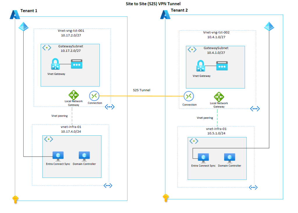
Please see the architecture diagram below which depicts our end goal. This example will utilise two different Microsoft Entra tenants and 4 subscriptions in total. This guide assumes that the infra VNets and virtual machines have already been provisioned:

Create Virtual Networks
A new VNet will need to be created to house the virtual network gateway in each tenant. This will be a dedicated virtual network for the virtual network gateway. Please note it is important to name the subnet: GatewaySubnet. You cannot use another name for the subnet.
If you would like to follow instructions on how to create a new VNet please follow these instructions: Create, change, or delete a virtual network.
Create Virtual Network Gateway
Create a virtual network gateway by following these instructions: Create a VPN gateway. For the Vnet details please refer to the architecture diagram above.
Create a Local Network Gateway
The local network gateway is technically a separate resource and component, but it works closely with a virtual network gateway. As per the diagram, a local network gateway resource must be created in both tenants. A local network gateway will signify the network in the other tenant. For example, when you create the local network gateway in Tenant 1, the setup process will prompt you for the following key details:
| Component | Value | Description |
| Public IP Address | e.g. 159.27.91.114 | This will be the public IP address of the virtual network gateway in tenant 2 |
| Address Space | 10.5.1.0/24 | This is the address space of the vnet-infra-01 VNet in tenant 2. This is required to allow the necessary traffic to the VNet across the tunnel. |
When creating the local network gateway in tenant 2, then you simply mirror the settings. e.g. for public IP address, state the virtual network gateway public IP from tenant 1.
Peering
You’ll notice that in each tenant the virtual network gateway VNets are peered to the infra VNets. This is a crucial step. Without this, it is not possible for the domain controllers in each tenant to communicate with each other. For step by step instructions to create a peering, please view these instructions: Create, change, or delete a virtual network
Important – Focus on the virtual network peering settings options. This will determine whether VPN traffic can reach VNets outside of the virtual network gateway subnet.
In this example, we will navigate to the virtual network gateway Vnet in tenant 1. Once you are in the peering section, click on add to configure a new peering.
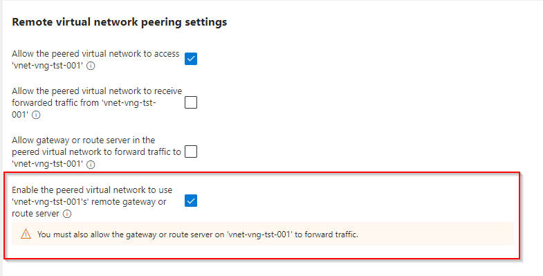
The critical settings here are the following:

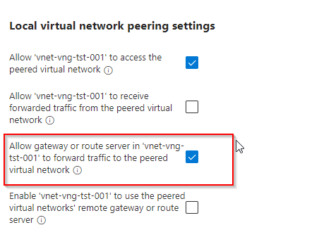
You must tick the last box as shown above. Once done, a warning will appear stating that you must also allow the gateway or route server on vnet-vng-tst-001 to forward traffic. As a result, scroll down and tick the relevant box as advised:

When the peering is created, then you must replicate the peering in tenant 2. This configuration will allow the infra VNets in both tenants to communicate directly with the virtual network gateways, as a result traffic will successfully get forwarded across the S2S tunnel to the Infra VNet in the other tenant. If the peerings are not configured using this method, then any workloads situated in the infra subnets will not be able to communicate across tenants.
Create a Connection
Once the peerings have been successfully configured, then a VPN connection can be established in each tenant. This can be configured directly from the local network gateway resources. Please view instructions here for more details: Create VPN connections.
The connection should now show as connected and workloads in each infra subnet will be able to communicate across the S2S Tunnel.
Conclusion
The S2S VPN tunnel will allow connectivity between the two different tenants, or even two different VNets if requirements specify. A critical configuration which can be overlooked is the peering setting on the virtual network gateway and workload VNets. Production workloads will most likely have numerous VNets, as a result, the traffic needs to be forwarded from the virtual network gateway to the relevant VNets. As long as you have established the correct peering, network traffic will filter as expected.

